
NOTICE: THIS DIY POWER METER
IS FOR MAKERS AND DO-IT-YOURSELF ENTHUSIASTS ONLY.
NOT A FINISHED PRODUCT. BUILD AND USE AT YOUR OWN RISK.
We were bored of talking COVID-19 all the time. We needed something fun. So we brainstormed and came up with a simple way to build a power meter in your kitchen.
Why?
- Because we could
- Because we always wanted to make power meters more accessible
- And because this may be an inspiration for new power meter manufacturers
What is it?
A fully functional spindle based power meter crankset based on a Shimano crankset. Performance is every bit as good as a commercial power meter.
The looks, waterproofing, and robustness is 100% up to you. We supply the electronic module (and strain gauges). You do the rest. We show you a very simple and basic way to do it.
This is where your creativity and skills come in – improve on our idea and share it to show how you want a power meter to look.
In no way is this a finished product and you are not allowed to make and sell these. This is Do-It-Yourself only. For those that find that fascinating, challenging, or whatever drives you.
DIY POWER METER INSTRUCTIONS
This is the simplest way we found to build a really good power meter based on our SG53 module. We have not included any waterproofing, so maybe you can call it the Corona/Zwift power meter edition 🙂
As with any recipe, make sure you read the whole thing before you start and make sure you feel comfortable doing each of the steps. We provide only paid support on this and encourage user-to-user support in a Facebook group set up just for this.
The steps
- Drill a small hole in the spindle
- Glue strain gauges onto the spindle
- Wire up the strain gauges and feed wires through the small hole
- Connect the electronic module (SG53) and battery
- Do preliminary calibration and adjust gain setting resistor if needed
- Finish up the power meter and do the final calibration
- Install on the bike
- Test and enjoy
That is all there is to it really. Let’s go through the steps in a bit more detail.
Drill a small hole in the spindle
We used a Shimano crankset with a 24mm spindle. These are steel and not easy to drill, so you need a really good drill bit. The best drill bit we know is a Phantom HM tip DIN 338N.
Make a 2 mm hole about in the center of the spindle.
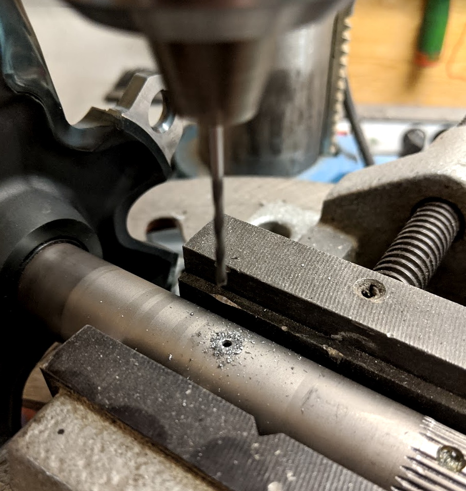
Preferably deburr the hole from both sides. It’s not easy on the inside, but there are tools that can do this.
Feeling adventurous? Consider installing the strain gauges on the inside of the spindle instead. This is entirely possible and a much cleaner solution. The hardest part you may find is inspecting the glue job after installation. If you go that route, using a crankset with a 30 mm spindle may make things a bit easier.
Safety note: Drilling a hole in a tube reduces its strength. You already know that, or you shouldn’t be building this. This hole will likely be where fatigue cracks set in if you ever get to that point. Not very likely (one user on Facebook actually did his own simulations on this to feel confident. As everything else DIY, you are on your own here. You build it – you break it – your problem 🙂
Glue strain gauges onto the spindle
Important: Before you glue the strain gauges install a 30-to-24 mm reducer on the spindle. You will not be able to do this later. This is actually very important. By using 30 mm bearings and a 24 mm spindle, you have a 3 mm extra radius outside the spindle for strain gauges and whatnot. This is plenty of room to do things as we show here. In a commercial power meter, you would do a neck-down and get a flush installation. This is not easy to do as DIY, so we use the 30-to-24 mm reducers. If you don’t have 30 mm bearings on your bike, you will need to change out your bottom bracket. This is easy to do and you need new bearings once in a while anyway 🙂
Gluing strain gauges is not that hard and you can find many tutorials on YouTube to show you how to do it. The simplest way we have found goes like this:
- Sand the area with fine sandpaper
- Clean and degrease with acetone
- Position the strain gauge using tape
- Lift the strain gauge and glue using one drop of Loctite 496
- Immediately press hard with your thumb and keep pressure for a minute
- Let cure (maybe to the next day)
- Carefully inspect under a microscope (poke it gently and ensure nothing can move)
We put two dual (shear-type) strain gauges on directly opposite sides of the spindle. As shown in the photo below (there is another strain gauge on the opposite side of the spindle oriented exactly the same way):
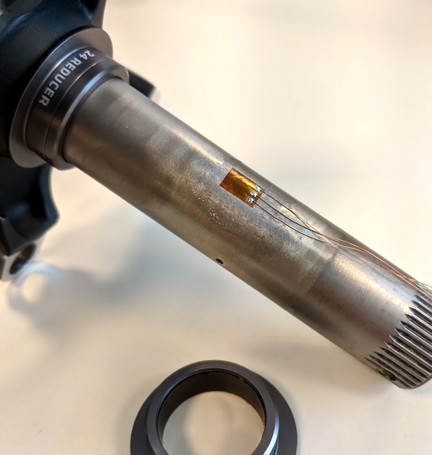
Don’t forget the reducers!
You would think the exact location and alignment of the strain gauges are extremely important. And it is important, but you can actually get pretty good results just eyeballing it. The calibration step will compensate for a lot of the “error” you make here.
Be really careful to inspect the strain gauge after the glue is cured. If it’s not a perfect installation, you have to redo it by sanding the area down again and starting all over. This happens once in a while for even the best.
It’s easy to work with strain gauges that have tiny wires already attached. If you get the strain gauges we provide, please do not try to solder directly on the strain gauges. That is not an easy job. Other types of strain gauges can be easy to solder, but these are definitely not.
Wire up the strain gauges
Make a small PCB to use as a connection point for the 2×3 wires from the strain gauges and the four wires going through the small hole. We did like this:
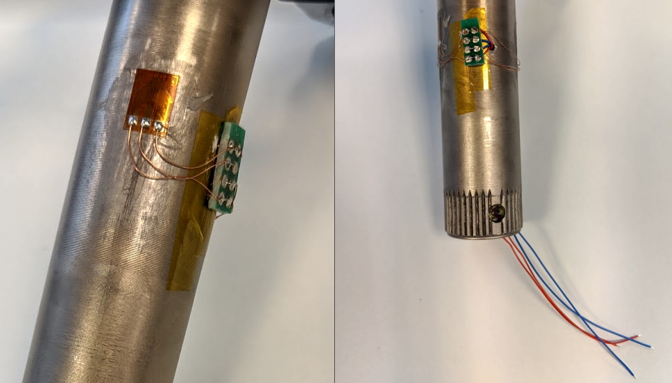
It’s not pretty, but it works. And it’s something you can do in your kitchen 🙂
The wires are hooked up like this:
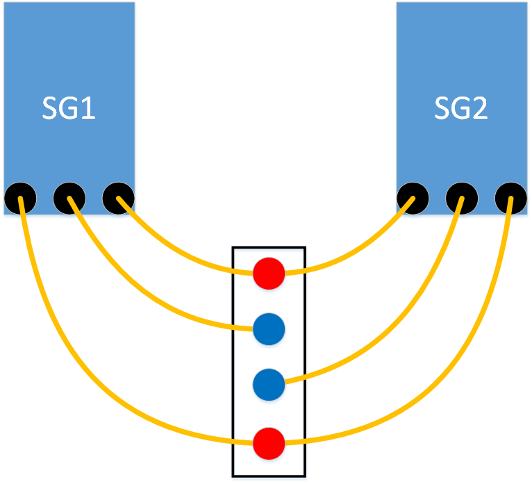
We have two red and two blue wires coming out of the end of the spindle. You can switch the two red ones around and the function is the same. The same goes for the two blue wires.
Connect the electronic module
Solder the four wires to the electronic module (SG53) as shown:
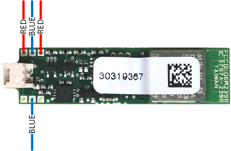
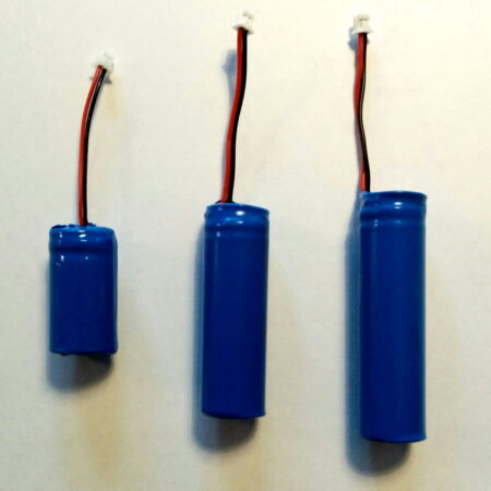
Connect a standard Li-Ion 4.2V cell to the white standard connector (or use the solder points on the other side of the PCB). There are many options for batteries. Pick one that works for you.
The battery cell can be charged using the micro-USB connector. The size of the battery can be pretty much anything you want. The active power consumption is about 1mA, so you get about one hour of battery life per mAh. A typical 250-400 mAh cell is a good size.
If the LED starts to flash rapidly after you connect the battery it’s a sign that something is wrong with the strain gauges. A slow green blink is normal and signals the power meter is turned on.
Do preliminary calibration
Check that you are able to connect to the DIY power meter using the standard Team ZWATT app (download from Google Play or Apple AppStore). You are going to need an Android device for the calibration steps, as the “secret” debug pages we use for that are only available in Android.
Enter “Developer Settings” in the app like this (here is a short video to show how you do this):
- Go to “Settings” all the way down on that page
- Tap 20 times quickly on “App Version” till you get the “Backdoor enabled” message
- Go back and select the new menu item “Developer Settings”
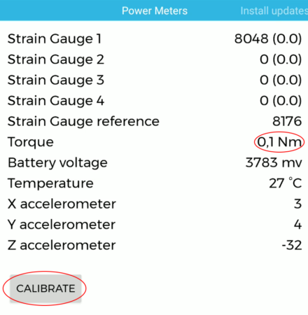
The first screen shows a number of important values. For the preliminary calibration, you simply tap “Calibrate” with no load and wait for that to complete. Then hang a known weight of 10-20 kg on the pedal (crank arm horizontal).
Read off the torque (in Nm) from the Developer Setting screen. We call this X.
Compare this to the actual torque you applied: Tq [Nm] = 10 [kg] x 9.82 [m/s^2] x 0.1725 [m] for a 10 kg weight on a 172.5 mm crank arm. We call the real torque Y.
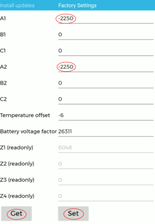
Now swipe right twice and tap Read to get the values. You want A1 (and A2, which should be equal). Calculate the new A-value like this:
A_new = A1 x Y / X
If A_new is in the range of 2000 to 4000 you should be fine. If not, you need to adjust the gain setting resistor (R3) as described below.
We do not consider the sign for A here. Positive or negative simply depends on how you connected the two red and two blue wires. Make sure you have positive torque showing when it should be positive – or simply flip the sign.
Adjust gain setting resistor R3
Find the new value by measuring the existing R3 value – let’s call that value R3_old. We can now calculate the new resistor value like this:
R3_new = R3_old x A_new / 3000
Carefully replace the gain setting resistor (R3 as shown below) with a nearby value and repeat the process to verify everything is fine. We use 0402 resistors, but you can shoehorn an 0603 onto the pads if you need to.

Also, see if you should change R10 as that sets the charge current. 7K5 is about 130mA. Don’t set less than 2K which is around 500mA and maximum for USB. This value depends on the recommended maximum charge current for the Li-Ion cell used.
Finish up and do final calibration
Here is your chance to really shine. This is where you craft the appearance of the power meter. Get creative with your 3D printer, make some nice woodwork, mold some plastic pieces, or whatever makes your power meter a true masterpiece showing off all your DIY skills.
Two areas need some care:
- Mid-section with the strain gauges. You want to protect that from moisture and also a bit for physical impact.
- Enclosure for battery and electronics. The antenna needs to be able to “see” the world and things should not bounce around but sit tight in the spindle.
Mid-section
For the mid-section, you will want some “cover glue” on top of the strain gauges. You can use epoxy or silicone. You also want to make sure the thin wires do not get cut by any remaining sharp-ish edges in the tiny hole. Fill the hole with glue to fix the wires.
On top of it all, you may want a decorative cover. A simple solution is shrink-wrap tubing (you can even get the one with glue inside, so the whole mid-section becomes watertight).

Some 30 mm spindle experiments.
Don’t look at the quick-and-dirty things we have done, but see if you can do something nicer. Use Plasti Dip, silicone, Sugru, or whatever you can make look cool 🙂
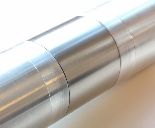
Nicer 30 mm spindle experiment.
You can also go fancier maybe with some laser engraved stainless steel. Let us see what you come up with for your DIY power meter.
Inside housing
Our first power meters had 3D printed housing to hold battery and electronics. That worked really well. The difficult thing is to make this waterproof. We trust your creativity here – this is a great place to show some craft skills.
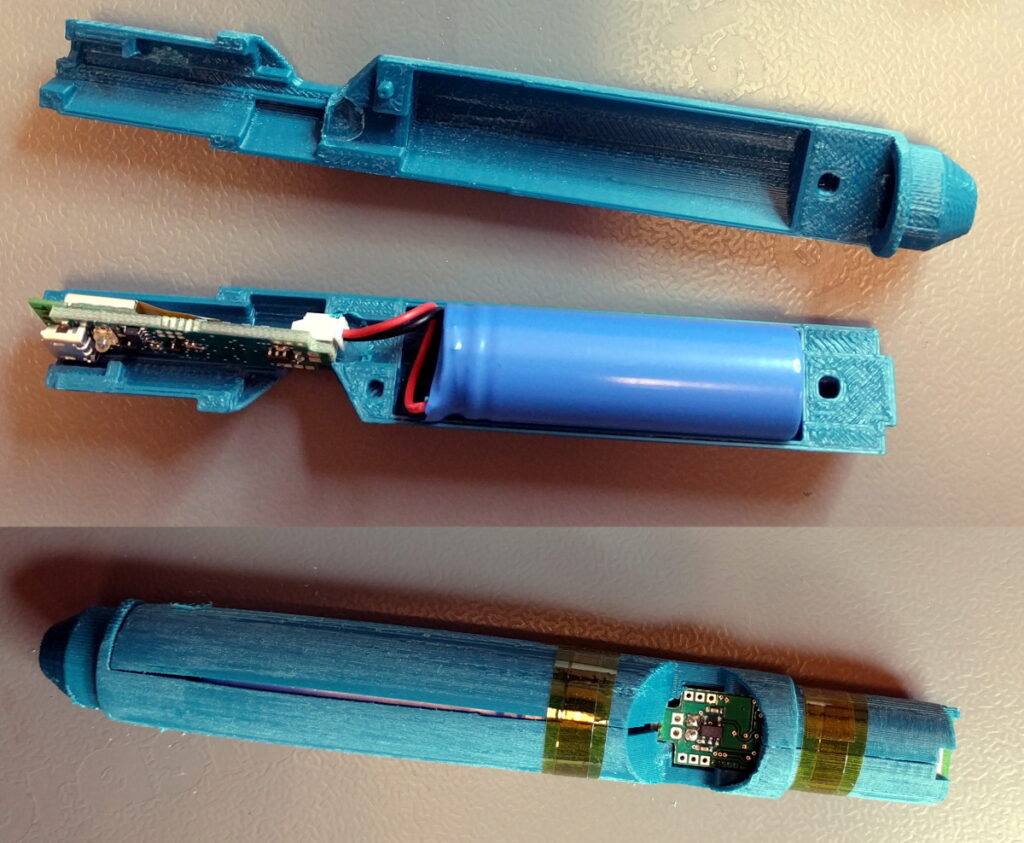
You can pick different battery sizes. If you want to go for a fully waterproof solution, you may want to think about “potting”. The biggest challenge is to make sure the antenna is sticking out and you still have a way to charge the battery. The LED is not 100% required, but quite handy for debugging and while charging. The standard method is a light-pipe/light-guide to send the light out to the front.
Install on the bike
When installing on the bike, you need to be a bit careful not to do damage to the mid-section with the strain gauges. You will obviously need 30 mm bearings, so the 30-to-24 mm reducers fit into the bearings 🙂
When taking the crankset off again, you need to be even more careful. You don’t want the reducer to hit into the mid-section with the strain gauges. We have used a bike with a BSA bottom bracket, so we can simply remove the right side of the BB as part of the uninstall process.
Test and enjoy
We have done a fair bit of testing on the DIY power meter and are quite happy with the performance. If you find the power reads a bit low or high you can increase or decrease A1/A2 in the Developer Settings. Usually, when we see errors they are however due to one of these things:
- Zero calibration problem (one or the other PM was not correctly calibrated before the test ride)
- Wrong crank arm length set
- Battery issue (mostly when using Garmin Vector as a reference like we do here)
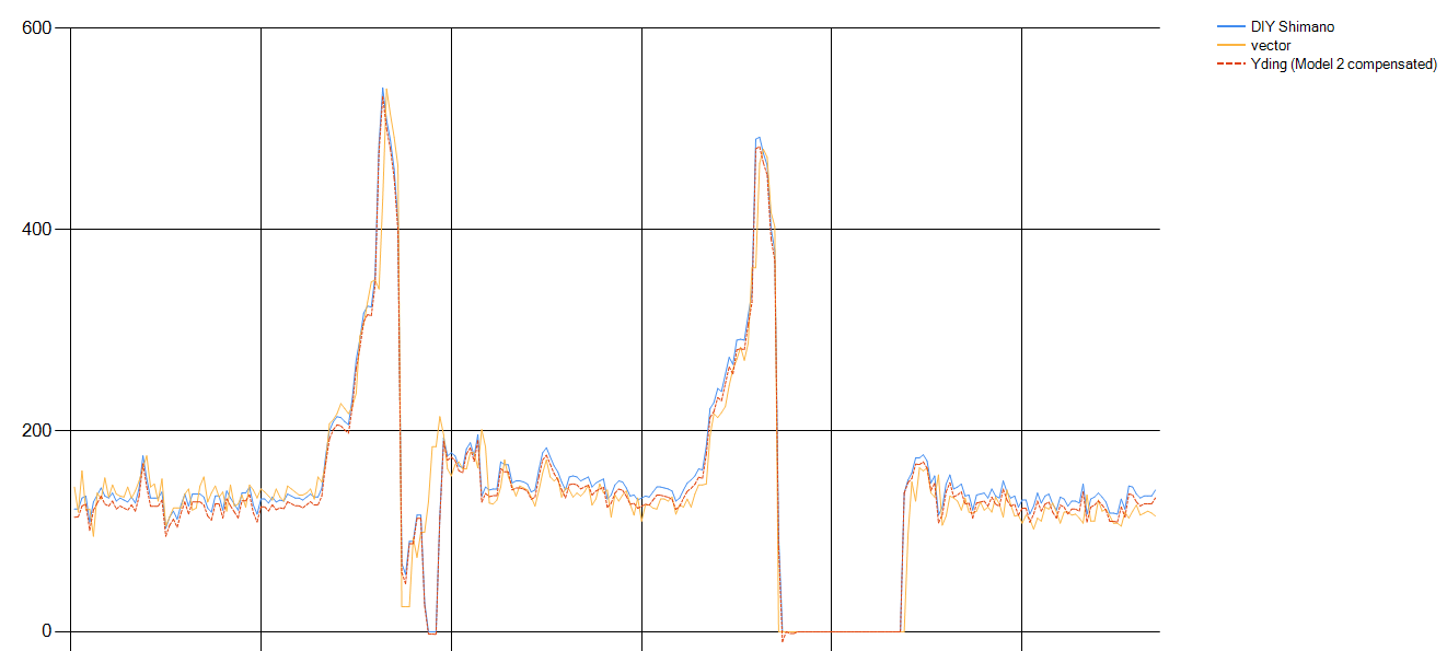
Have fun and please share pictures of your build. Use #diypowermeter so we all see it.
HOW TO GET THE PARTS
Most of it we leave to you, but these are the bits we can help you with:
- The SG53 module
- Some useful strain gauges
UPDATE Sep 2020: We just got a new box of modules back from a manufacturer. These modules are 100% up to the normal standards we deliver. They even have the conformal coating applied to them for better moisture protection.
UPDATE Jan 2021: We dropped the minimum bid for one module from €150 to €100 for a limited period.
UPDATE Jan 2024: This is still running and people are still building their own hobby power meters. There are still modules in our box and they are 100% up to normal standards.
Put in your details below to get your modules – we will be in touch for payment and shipping details.
Thanks for playing along.
ORDER YOUR MODULE(S)
We will add shipping costs depending on where in the world you are (€10 to €50). We mostly ship with GLS in the EU and UPS out of the EU.
Note: If the form does not show, please try this alternative page.
Want to do more?
It is no secret that our main business is not DIY power meters. We do advanced sensor technology and consulting on torque sensors, brake sensors, and power meters.
We can also provide professional-level engineering support for this. Our standard rate is €800 for a 5-hour support package. For DIY, we encourage peer-to-peer support in this specific Facebook group set up for that.
If you want to start manufacturing power meters – may be inspired by this DIY project – please get in touch using the form below. Our offer to sell you a license to manufacture power meters using our technology for down to around $10+crankset is still standing. You should be ready to manufacture batches of at least 10000 units and pay the one-time license fee for the technology for this path to viable. If you are planning a smaller scale manufacturing, get in touch and we can work out a deal where we manufacture the electronics for you.
 SENSITIVUS GAUGE