[DEUTSCHE VERSION] | [VERSION FRANÇAISE] | [中文版本]
E-BIKE TORQUE SENSOR MARKET
Why is the e-bike torque sensor such an important component? This is what we dive into here. Bicycles with electric motor assist are gaining popularity and are a very fast-growing market. More than 3 million e-bikes were sold in the EU in 2019, and between then and 2021, the sale of electric bicycles was boosted by 240% (known as the COVID Bike Boom). And the sale of e-bikes continues to climb especially in Asia and Europe.
However, safety is a growing concern. The rapid growth also leads to an increased number of accidents involving e-bikes.
Sensors can improve safety
It is clear that this requires improvements. The industry is responding to this. Anti-locking brakes on the front wheel are one such technology. Another important area to improve is the control system for the motor, which ideally should respond fast, accurately, and predictably. This improves the handling of the bike making it much more intuitive and enjoyable to ride, while also making it safer.
Definition: The difference between an e-bike and a pedelec is simple. While a throttle may control an e-bike, a pedelec requires the rider to actively spin the crank by putting force into the pedals (legal rules). In practice, however, the term e-bike is often used for both types of bicycles.
KEY CHALLENGE: THE TORQUE SENSOR
The first wave of e-bikes relied on simple cadence-based control resulting in quite unpredictable handling when cornering and during start/stop. Complementing this with a torque sensor to sense the force put into the pedals is a significant improvement. This is why the industry is chasing the ideal e-bike crank torque sensor to fulfill the requirements:
- Low latency (max 10ms sensor delay)
- Accurate (1-2% like a sports-bike power meter)
- Maintenance-free
On an e-bike, the torque sensor measures the applied pedaling torque of the rider and sends it to the controller of the e-bike along with cadence information. Based on this information an algorithm controls the motor speed and power. The performance of the e-bike as perceived by the rider depends heavily on the precision and accuracy of the motor control.
As with any other system, good performance starts with good quality input signals. The torque measurement in the sensor is a key component of the input to the controller.
Read on to learn how the different technologies stack up in this game.
STRAIN GAUGE TORQUE SENSOR
The strain gauge technology was invented in 1938 and has been the workhorse of the entire industry for ages. This tried and trusted method is so well understood today that it is the reference for the other methods presented. Strain gauge torque sensors are in 100% of the popular power meters on sport bikes today. By using a standard dual strain gauge configuration, temperature sensitivity can be negligible.
Some of the advantages include very low power consumption and superior dynamic range. The primary disadvantage has been the need to somehow connect electronics on the rotating part to the stationary motor/controller electronics. Recent advances have significantly reduced this challenge.
TRADITIONAL SOLUTION
The traditional solution places a strain gauge on the rotating shaft/spindle with a high gain amplifier. The output signal transfers to the stationary parts through the use of mechanical slip-rings. This is obviously a reliability and maintenance issue and not the preferred solution.
INDIRECT MEASUREMENTS
Placing the strain gauge on a stationary part (frame, the outer shell of a bearing, or similar) and measuring other strains correlated to the torque applied solves the connection problem. Unfortunately, the forces can get quite complex in some e-bike frame and motor designs, making this a very difficult solution.
NON-CONTACT SOLUTION
Combining strain gauge technology with other tried and trusted technologies like RFID, contactless power and data transfer enables an e-bike torque sensor without the disadvantages of the other solutions. The rotating part with the strain gauge glued to the shaft/spindle is being read off by a small electronic circuit. This communicates with the stationary part through the air – just like a contactless key card, payment solution, or ski pass. The stationary part of the sensor is at the same time providing the wireless power and picking up the data signal from the rotating part. Air gaps up to 1.6mm are possible making the mechanical integration fairly straightforward and maintenance-free.
This is the technology selected for our contactless torque sensor module.

MAGNETOSTRICTIVE
Magnetostriction (Wikipedia) is a property of magnetic materials that causes them to change their shape or dimensions during the process of magnetization. This can be used in reverse to create a torque sensor.
Cobalt exhibits the largest room-temperature magnetostriction of a pure element at 60 microstrains. Among alloys, the highest known magnetostriction is exhibited by Terfenol-D. Other ferromagnetic materials can be used as well.
Two basic variations of this technology are passive and active. None of them require any electronics on the rotating shaft/spindle, which is the key advantage of this technology.
PASSIVE MAGNETOSTRICTIVE
Passive magnetostrictive technology requires a rotating shaft/spindle made of special hard-magnetic steel alloys with a special magnetic signature. This “special treatment” complicates the manufacturing process. When measuring small torque values, the changes in the magnetic field is comparable to that of the earth’s magnetic field. High sensitivity requires additional magnetic shielding or complex compensation for changes in the bike’s orientation relative to the earth field.
Peripheral irradiated magnetic fields can also severely disturb the very small and susceptible measuring signals. This inhibits the measuring capability of torque detection.
Another problem is that magnetization degenerates with time. This degeneration accelerates by higher temperatures and possibly also by higher loads on the shaft/spindle.
ACTIVE MAGNETOSTRICTIVE
In the active magnetostrictive principle, the magnetization is supplied on the fly by the sensor. The shaft/spindle does not need a special magnetic pattern to be magnetized in during manufacture. Compared to the passive principle, this saves the “special treatment” process at the expense of more complex electronics and higher power consumption.
The sensor induces a magnetic alternating field into the ferromagnetic shaft/spindle and measures the resulting magnetic fields with secondary inductors. A change in the susceptibility and thus the magnetic resistance results in a change in the magnetic flux. This magnetic flux change is detected by the secondary inductors and through a complex digital signal processing algorithm converted into a signal which is proportional to the torque.
On top of the challenges mentioned for the passive principle, the inhomogeneity of the ferromagnetic properties in the shaft/spindle complicates this method. Adding a quite elaborate and time-consuming calibration step into the manufacturing process can somewhat compensate for that. Higher accuracy can also be achieved by increased power consumption and more advanced calibration. This method is also sensitive to temperature changes.
OPTICAL
Optical sensors are always susceptible to contamination on the lenses etc. This makes the optical principle less useful in an e-bike torque sensor application. Grease and oil are used in the motor unit, and for the cranks and bearings in the exact area where the sensor is placed. This alone makes the optical principle less useful for this application.
On the positive side, the optical principle may not require any electronics on the rotating parts.
ACOUSTIC
Several different acoustic principles exist for strain sensing and are being used to some extent in aerospace. Changes in strain or temperature cause shifts in the acoustic wave speed, which the acoustic sensor can detect. Coupling the acoustic signals on and off the rotating shaft/spindle is a complex mechanical challenge and this principle is not really a contender for the e-bike torque sensor.
Some advances in the research suggest viable acoustic wave-based alternatives sometime in the future. However, experience from other technologies tells us this can be 5-10 years out as the transition from research to the industry can be quite slow.
MAGNETIC FIELD STRENGTH SENSOR
This principle is very cost-effective for linear distance measurements. A hall effect sensor measures the distance to a permanent magnet by measuring the field strength. The big challenge with this type of sensor is that the field strength follows a d^3 function. This limits the dynamic range of distances. In e-bikes, this principle has only been used for hub drive solutions (motor in the hub of the wheel as opposed to the crank area). Due to the range limitation, this seems to be difficult to use this principle with the pre-tension required for a belt drive.
E-BIKE TORQUE SENSOR COMPARISON
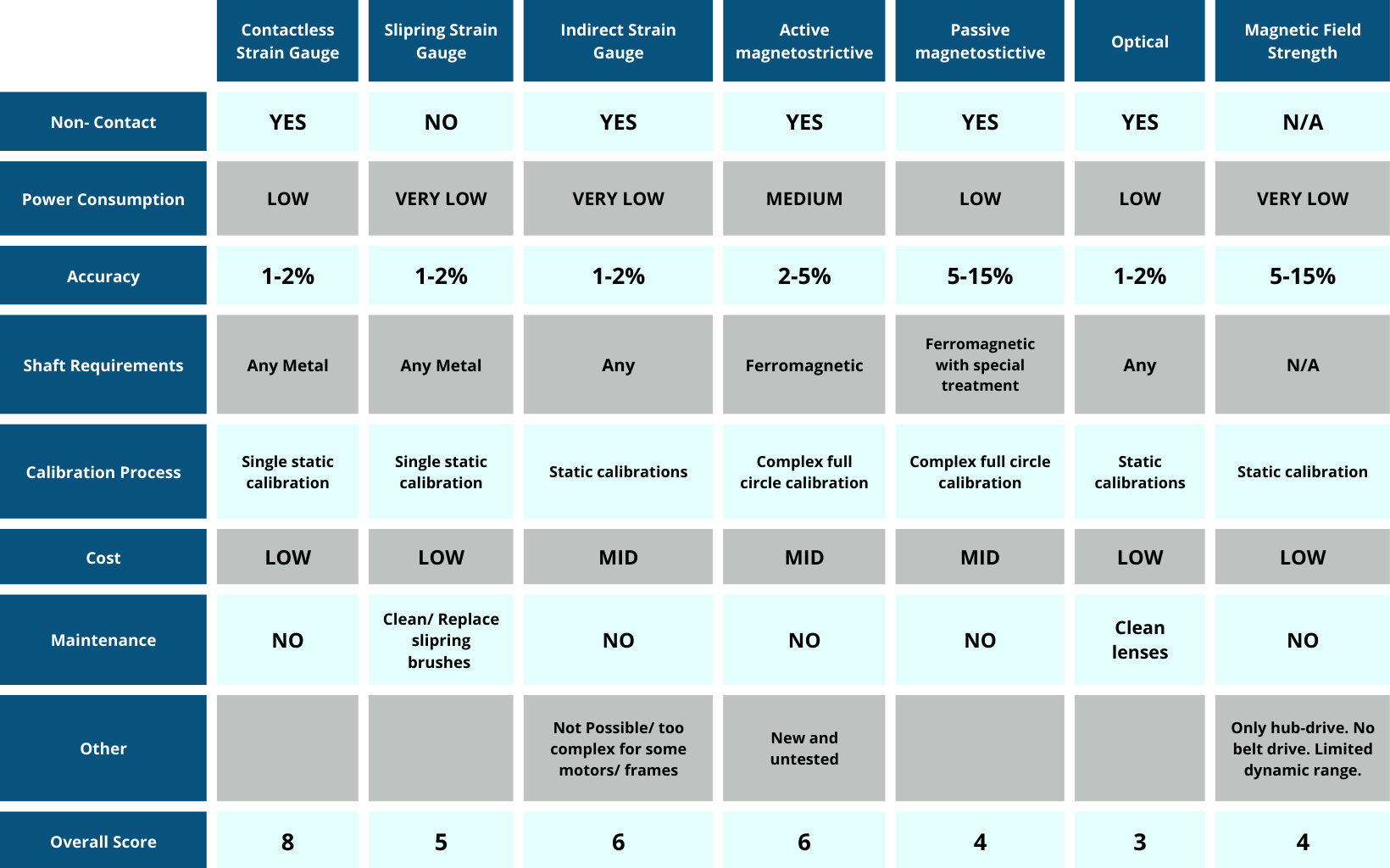
As evident from the overview table, the contactless strain gauge sensor is a quite favorable solution for many e-bike applications. The main disadvantage is that the rotating part needs additional electronics. Since the cost of electronics goes down all the time, this is a minor disadvantage.
Practical e-bike torque sensor solutions in use today are based mostly on the passive magnetostrictive principle with limited accuracy. A shift toward contact-less and indirect strain gauge systems will secure higher performance and safer e-bikes in the future.
[DEUTSCHE VERSION] | [VERSION FRANÇAISE] | [中文版本]
FAQ
EU regulation requires an e-bike to only provide assistance when the crank is turning. The cadence sensor typically satisfies this requirement. The cadence sensor combined with the torque sensor simplifies the system.

 SENSITIVUS GAUGE